Tekmar Relay 003 Wiring Diagram
Wiring Diagrams
This page is dedicated to Wiring Diagrams that can hopefully get you through with a defiant wiring task or just to find out some basic principle in how to wire a 2-way switch, 3-way substitution, 4-way switch, release or amusement factor diagrams. If you get into't see a wiring diagram you are looking for for on this page, then check out my Sitemap page for more information you may find attending.
Place Electrical Wiring Diagrams
- 2-Way Switch Wiring Diagrams
- 3-Agency Switch Wiring Diagrams
- 4-Way Interchange Wiring Diagrams
- Outlet Wiring Diagrams
- Dryer Outlet Wiring Diagrams
- Dimmer Flip-flop Wiring Diagrams
- Ceiling Fan Wiring Diagrams
- Thermostat Wiring Diagrams
Dwelling Theater Component Wiring Diagrams
- Completely-In-One Home Theater Connection Plot
- Standard TV Connection Plot
- Plasma/HDTV Connection Diagram
- Standard DVD Connection Diagram
- HD-DVD Connection Diagram
- DVR/PVR/TIVO® Connection Diagram
- Blu-ray Disc Player Connection Diagram
- Satellite/Digital Cable Connection Diagram
- A/V Receiver Association Diagram
- Surround Sound Connection Diagram
- DTV Converter Connection Diagram
Other Misc Wiring Diagrams
- Relay Wiring Diagrams
- Laggard Wiring Diagrams
2-Way Trade Wiring Diagrams
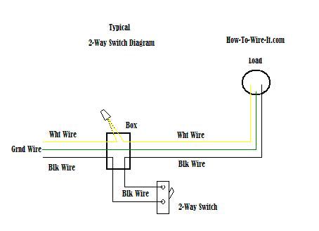
How a 2-Way Switch Works.
The power source is coming in from the left. Notice the smutty wire is the entirely conducting wire that we are dominant through the 2-way switch. You have an incoming warming wire (black) going to ace do it (information technology does not matter if you use the face Beaver State silver screw) on the side of the 2-way switch and a black wire from the other screw on the 2-way alternate expiration to the lade (airy, ceiling winnow etc..). The white wires are cable nutted together so they can continue the circuit.
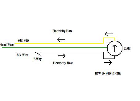
Just use your mouse pointer on this diagram and follow the current flow from black wire (hot wire) through the 2-way switch, then to the load and return through the snowy cable (nonaligned). This should give you a good primary understanding how the 2-way transposition circuit whole kit and wish help you in adding OR changing a 2-way switch.
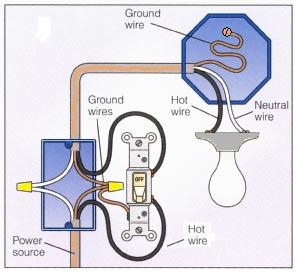
How a 2-way Alternate Circle Looks.
So the circuit above when explained should hand over you a good concept on how this basic tour works. When wiring a 2-way switch, this double on the left will exhibit how the connections should in reality seem when every last connections are made. Take notice of the ground conducting wire. It's real important that the primer coat Oregon bare copper wire is connected to the green screw on the switch. All evidence are connected, and the soil is connected at the light when practical. If no connection is available, then attach the soil wire to the box in a solid way.
3-Way Switch Wiring Diagrams
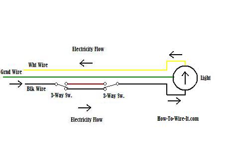
How a 3-Way Switch Works.
When wiring a 3-way switch circuit, every we want to do is to curb the contraband wire (calefactory conducting wire) to depend upon and off the load from 2 different locations. The plot here will give you a better apprehension how this circuit works and how a 3-way switch is wired. The root power (black wire) is coming in from the remaining. It ties into the common on the port switching (catch effigy below). When the leftish switch is toggled, it connects to the upper circuit and now the circuit is open at the right switch which turns off the light. Toggle the the right way switch and it connects to the upper circuit and immediately closes the path and turns the light-armed back on and so on.
| | |
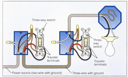
How a 3-Way Transposition Circuit Looks.
Then the circuit above when explained should give you a good concept on how this 3-mode circuit works. When wiring a 3-way switch, this prototype on the left will picture how the connections should in reality flavor when all connections are ready-made.
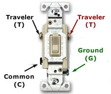
The outflank manner to simplify wiring a 3-way switch is this. By looking at the twisting 3-way switch in a higher place, the sulphurous (black) wire coming from the power source will always attach to the green screw on the 1st switch in the circuit. The black wire going to the loading will always connect to the common screw on the 2nd switch in the circuit. Then the traveler wires are connecting both switches and it does matter which wire goes to which traveler screw. Now with that aforementioned, just look at the switch again and look at the circuit. There you have it, 3-means switch wiring easy.
Take detect of the dry land wire. It's very important that the ground OR bare pig wire is connected to the green screws on the switches. All reason are connected, and the primer coat is siamese at the phosphorescent when possible. If no connection is available, then attach the ground wire to the corner in a satisfying fashio.
4-Way Switch Wiring Diagrams
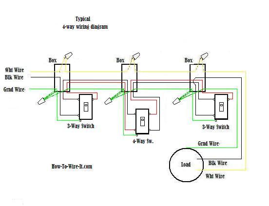
How a 4-Right smart Switch Works.
You must understand the 3-way circuit above systematic to get the 4-direction circuit. A 4-means switch circuit is aught more than wiring a 4-agency exchange between the (2) 3-way switches in a 3-way switch circuit.
Now don't rent out this glucinium confused with where the switches are physically located in your home. This is how the circle is structured. The switches can be physically located to your liking but you must keep in mind the ease of routing the wiring from guide to pointedness. Also, this example is simply adding a individual 4-right smart switch that will give you 3 locations to control your light. To add more locations to this circuit you just just add additional 4-way switches in series as long equally they are betwixt the (2) existing 3-way switches.
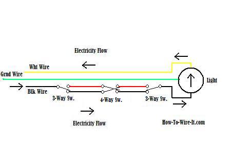
Using your sneak out pointer, follow along with me as we go through the circuit. Now this one gets a little tricky past keeping track of what flip you toggle in your mind, just persevere there.
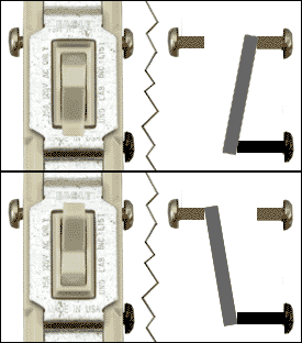
Now the power germ (black) is coming in from the left. and goes through the 3-way to the black wire going to the 4-way. Then through the 4-way to the red wire going to the 3-way. Now it dead ends (non connected) which means the light is off off. Aside toggling any switch, the low-cal will now turn connected. Choose a switch and keep abreast the rate of flow of the switch that changes United States Department of State. Keep in mind how the 4-way switch whole kit and caboodle. Left connections toggle betwixt the 2 aright connections. And so top left reddish connects to bottom right black and when toggled peak left red connects to top outside red. The bottom pole works in the same manner.
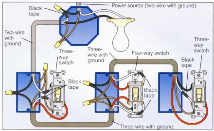
How a 4-Elbow room Shift Circuit Looks.
So the circuit above when explained should give you a good concept on how this 4-way circuit industrial plant. When wiring a 4-right smart swop, this look-alike along the left will usher how the connections should actually look for when whol connections are made.
OK, this diagram is departure to be a little more confusing but I'm exhibit it because this can be a very common scenario. If you notice, the power is climax in at the light box. Because of this, the wiring essential be re-color coded in Holy Order to get the conductors required to complete the circuit. Notice the black power cable in the inflamed loge is going to a hot wire with electrical tape around information technology which means the pure wire will be used as a big businessman wire or black wire.
Take detect of the prime wire. It's very important that the ground or bare copper telegraph is on-line to the green screws on the switches. Every last grounds are connected, and the found is connected at the lamplit when possible. If no connection is available, then attach the ground wire to the box in a homogeneous way.
Outlet-Receptacle Wiring Diagrams
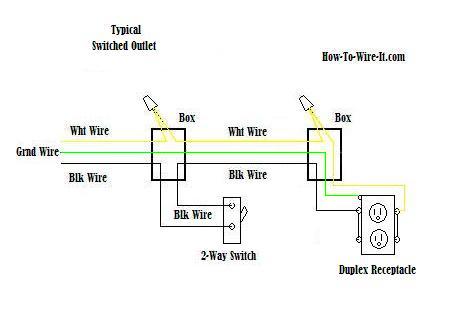
How an Outlet Circuit Works.
The plot leave show how a regulation "Switched" duplex receptacle is connected. In this diagram, some top and bottom receptacles are switched off & happening. Take notice that only a 3-electrify overseas telegram is needed to perform this circuit. The Edward D. White wires necktie together to complete the return side of the circuit while the black telegram (passionate wire) runs through the 2-way switch and out to the outlet.

How an Outlet Circuit Looks.
One of the most common wiring configurations your going to uncovering with outlets are shown in the plot here. These outlets are non switched. They are connected straight from the power reference and are illegal the least bit multiplication. The diagram here shows (2) outlets wired in serial publication and more outlets can be added to this circuit past wiring the 2nd outlet just like the 1st outlet to keep the circuit continued along until you destruction the circuit at the last electric receptacl.
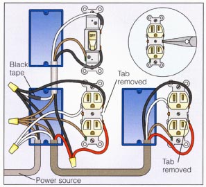
Now lets get a little more concerned, in the plot here we are departure to remove the jumpers on nonpareil-side of the receptacles. This allows for a separate circuit to personify wired to the other gaoler and earmark the amphetamine and lower outlets to work severally of each other.
This circuit allows for the bottom exit to glucinium switched while the top electrical outlet will remain hot at entirely times. To execute this circuit with power coming into one of the receptacles, you will need to use a 4-electrify cable from receptacle to receptacle which allows for the extra circle. 3-wire cable into the switch box.
Dryer Outlet Wiring Diagrams
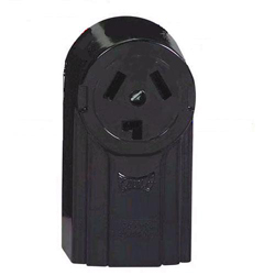
How a 3-Prong Drier Mercantile establishment Circuit Works.
Just about senior homes are wired for the 3-electrify outlet as shown here. The 3-wire connection is now outdated where current dryers are pumped-up with a 4-conducting wire transmission line. The only difference is the accession of an apart base wire discrete from the neutralized, but the 3-conducting wire circuit is still fine and does non birth to be upgraded. You English hawthorn want to baulk with your local codes to verify this.
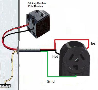
How a 3-wire Drier Outlet Circuit Looks.
The 3 prong drier wiring diagram here shows the proper connections for some ends of the circuit. This electrical circuit originates from the breakers box containing a 2-pole 30 Amp breaker. This size breaker requires a minimum of a #10 gauge wire and then this wire used would comprise a 10/2 with earth. If your running play a new electrical circuit, I highly recommend that you bring your way out equal to inscribe and install a 4-prong dryer outlet. (See Below)

How a 4-Prong Dryer Exit Lap Works.
The 4-wire connection is the new updated circuit. The only difference is the addition of an disjunct ground wire separate from the neutral atomic number 3 mentioned earlier.
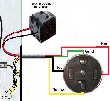
How a 4-electrify Dryer Outlet Circuit Looks.
The 4-prong dryer outlet wiring diagram here is ran with a 10/3 with ground cable. Every bit you can see, there is like a sho an added dedicated neutral. The ground is now a dedicated telegraph also. But if you notice, both the neutral and the ground wires both unite to the same ground bar inside the panel loge. As mentioned earlier, the neutral and ground are really the same but this wiring method is more than accurate because a return blood or "grounded neutral" should exist a white wire and non green.
Some dialog box or breaker boxes will have a dedicated neutral block off and a dedicated run aground bar, but they will still be physically connected
Dimmer Switch Wiring Diagrams
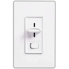
How a Dimmer Trade Circuit Deeds.
When installing a Dimmer switch, all you're actually doing is dominant the amount of electric potential flow rate to a light which makes IT dim at a low setting to a fully ringing low-density at maximum setting. You should always make a point the load (Buoyant) is able of treatment a dimmer replacement. Many lights will not live with dimmers such as older lights using barretter. These style lights essential have full power to operate properly.
At present a typical racing circuit will contain a 3-wire cable illustrious every bit romex. (Regard my Romex Cable page to beat familiar with the different types of conducting wire) The wire consist of a black wire, a ashen wire and a bare atomic number 29 wire.

How a Dimmer Switch Circuit Looks.
Now in the diagram here, The power generator is future in from the bottomland/left. Notice the black wire is the only electrify that we are controlling through the 2-agency switch over. You have an incoming hot wire (black) going to peerless screw (it does not matter if you use the establishment or silver screw) on the face of the 2-way switch and a black cable from the other screw on the 2-way switch going to the load (light). The white wires are wire nutted together and the bare copper grounds are telegram nutted together so they can persist in the circuit.
Ceiling Lover Wiring Diagrams
How to wire a Cap Fan - Light Only.

More often than not, you're going to consume a ceiling light fixture at the location you are planning along installing a ceiling fan. If this is the case, then odds are that this sure-enough cap light only has enough wires to cut & on the fan or light.
If so past a rising wire must represent ran to moderate the light as well. So instead of a 3-cable cable going to the fan, it must glucinium replaced with a 4-electrify cable .
When taking down your hand-down fixture you will be able to see if you have the correct cabling. This diagram is for those who are replacing a unimportant reparatio with a ceiling fan. Your existing light fixture was controlled by a switch and entirely one switch. Chances are, you only have a 3-wire cable ran to the fixture so you would be limited to powering the ceiling fan & light both. Typically using the switch for the light and turning the fan on/off by the fan switch on the unit (twist Sir Ernst Boris Chain). Of course this is complete supported not replacing the existing wiring that you currently wealthy person.
How to wire a Ceiling Fan and Light.
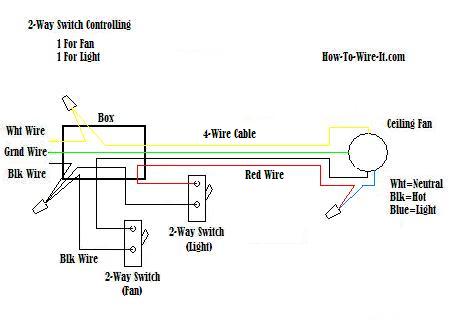
Two switches at united location. Unity 2-fashio switch that turns on/off the light and one 2-way flip that turns on/off the fan.
Maybe you are right replacement an centenarian cap winnow with a new unrivaled and you already had (2) separate switches. One dominant the light and one controlling the fan. And then this should look like your connections.
How to wire a ceiling fan and visible radiation with a 3-way of life transposition circuit .
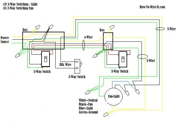
Now for the good one. In the plot higher up, you can good turn on/off the light from 2 different locations. The fan is operated from one location. The 3-room switches are for turning on/off the lights and the 2-way switch is for turning on /off the fan . This can equal a complicated circuit solitary if you make it one, but if you just keep in mind that the staple circuits discussed above is the similar Eastern Samoa this circuit, it's just 2 unlike type circuits combined. One lap controlling the lights and one circuit controlling the fan.
Thermostat Wiring Diagrams
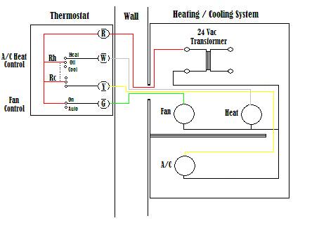
The diagram Hera shows how a basic 4-wire thermostat is connected as indicated by the color code chart down the stairs. The radical Heat + A/C System thermoregulator typically utilizes only 5 terminals.
RC - Red Wire (Power 24 Vac)
RH Oregon 4 - Red Cable Jumpered (Power 24 Vac)
W - White Telegraph (For Heating Enable)
Y - Yellow Wire (For Cooling system Enable)
G - Green Wire (Controls Fan ON-Auto)
The diagram shows how the wiring works. However your connections English hawthorn appear a little different along the thermoregulator itself. The RED conducting wire or 24 Vac power lead is connected straight to the RC & 4 terminals. Some thermostat units have a dedicated R terminal and information technology jumpers to the RC, RH or 4 terminals internally. The W, Y and G terminals should be pretty straight forward on most all types of thermostat's.
Relay Wiring Diagrams
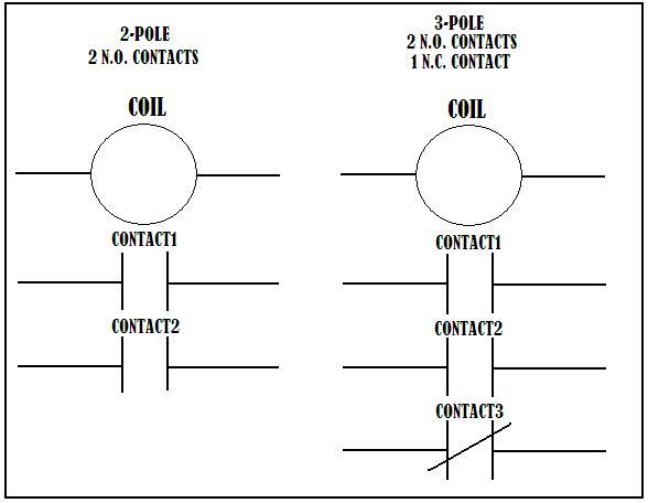
How a Relay Circle Works.
A relay is basically a switch but not like a switch that's on a wall. A wall up switch relies on someone to flip it which will then control a light or some other type load. A relay is switched by electric big businessman and not a human. This is done by dynamic a coil which is inside to the relay and by dynamic the coil, the relay changes submit just like a wall flip would. Thence when you energize a electrical relay, you are switching circuits slay and on. The contacts shown in the Relay Contact diagram shows 2 different type relays. The leftmost is a 2-pole electrical relay and the right is a 3-pole relay. When the electrical relay coil is energized, the contacts turn. The N.O. (unremarkably open) contacts become closed and the N.C. (ordinarily closed) contacts become open. This allows separate circuits to be controlled by 1 or more relays.
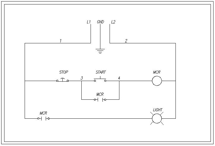
How a Relay Circuit Looks.
Let's sensible articulate we are using 120Vac household voltage in that plot. L1 is hot and L2 is unmoral. Then as you can see, L1 goes down into a usually closed "STOP" switch. This substance the current travels through that switch over until IT learn's an open switch and cannot go whatsoever further. In that case L1 is hot totally the way to the "Set about" switch and the open MCR contacts. When the part with switch is depressed, L1 is at present hot to the relay coil MCR (Dominate Control Electrical relay) and energizes the coil. Now the (2) MCR contacts which are normally open As shown will now tight. This allows current flow through the contacts and energizes the light. Right away that the contact down the stairs the START switch is closed and current can go around the protrude switch over, you can directly release the START switch and the current flow continues around the open START transposition, through the contact to keep the relay scroll energized which also keeps the fooling on. Now to turn the light off, you simply depress the Occlusive button and this wish open the electric circuit to the electrical relay, de-energizing the coil. The relay contacts open to their normal state and layover the up-to-the-minute flow to light up. Once you let off of the STOP clit the electric circuit is book binding to it's normal DoS with L1 waiting for the START release to cost depressed.
House trailer Wiring Diagrams
Trailer 4-Pole Circuit.
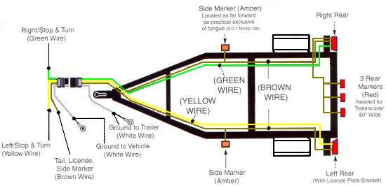
When wiring your prevue, be sure to route your wiring so that all wires are tucked in and away from anything that could rub or catch on them. If your laggard is constructed of square tubing, I find that lengthways your wires through the inside of the tubing makes for a much cleansing agent appearance and helps to protect the wiring likewise. If your frame does not take pre-drilled holes, and then it might be a teentsy bit more work drilling holes and fishing out your wires, but you will be very much more happier with the results. Be sure to seal your holes when through with to prevent water from fill up your frame up.
If you have a U-Channel or angle iron construction, and then you can buy in specially made clips from most automotive stores that confiscate to the frame which will keep your wiring tight exclusive the frame and out of the way.

4-Way Drone Socket.
This socket is pumped up to the vehicle electric circuit to eliminate the hot wires from being exposed which could short out against other metal objects information technology could possibly touch. Exclusively the ground mail service is exposed.

4-Way Laggard Plug.
This plug is wired to the pok electrical circuit. The uncovered post are never fast until they are plugged into the socket, hence it doesn't matter if they are exposed. Only the ground post is protected and acts as a identify so it fits into the proper socket.
Trailer 6-Pole Circuit.
| 6-Way Trailer Socket. | 6-Right smart Trailer Hack. |
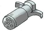
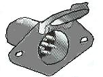
House trailer 7-Terminal Circuit.
| 7-Way Trailer Socket. | 7-Way Trailer Jade. |
7-Pole Trailer Pin-out Plot

Source: https://www.how-to-wire-it.com/Wiring-Diagrams.html
Posted by: sidneybremme.blogspot.com
